

Bias Voltage diyAudio
What is Bias Voltage
VIDEO Understanding Bias Voltage

PPT Bias Voltage Generation PowerPoint Presentation free download

Voltage Bias Generating Circuit Download Scientific Diagram

Simplified Schematic for Bias Voltage Calculation The appropriate
70+ Images of What Is Bias Voltage Automotive
Gallery of What Is Bias Voltage Automotive :

Current bias voltage characteristics of Device 1 a Measured

a Current across the device at bias voltage V bias 1 mV versus gate

a Current across the device at bias voltage V bias 1 mV versus gate

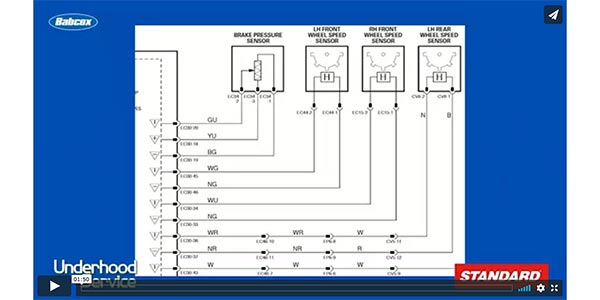
Understanding bias voltage diagnostics for sensors
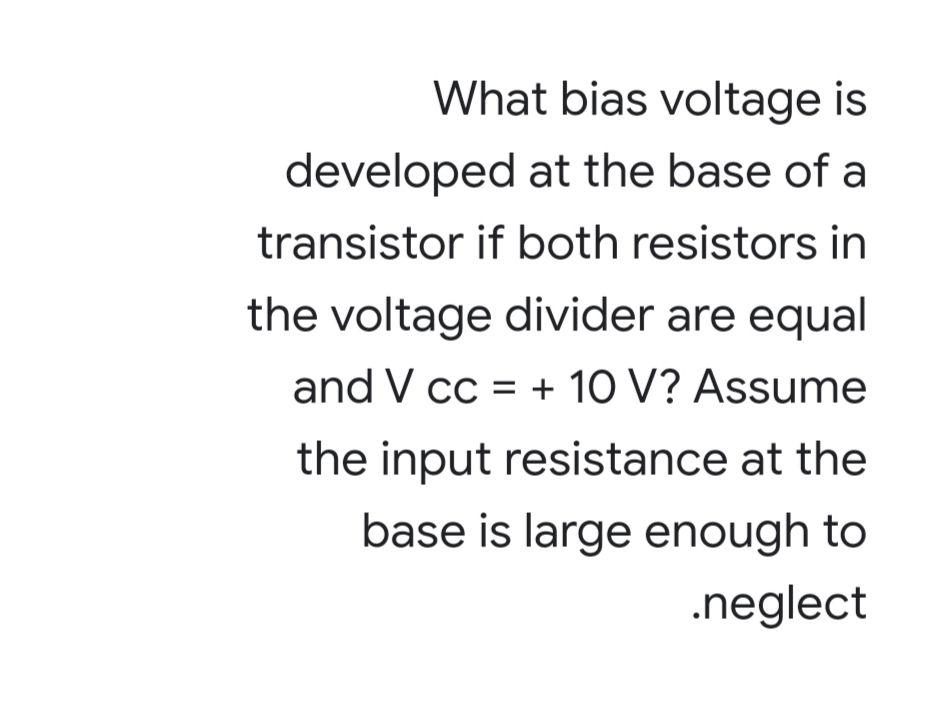
Solved What bias voltage is developed at the base of a Chegg com

Dependencies of bias current Ibias on the bias voltage Vbias at various

The bias voltage output at v w 0 Download Scientific Diagram

The effect on the signal of the bias voltage Download Scientific Diagram
Current as a function of bias voltage for Download Scientific Diagram

Three typical types of bias voltage V schemes a The floating bias
Current as a function of bias voltage for Download Scientific Diagram

and Fig 2 A bias voltage of 1500 V was applied to the detector with

Target bias voltage changes with different impurity additions Electron

The bias voltage that is used for the different sensors and the number

Simplified schematic of a dynamic voltage bias Download Scientific

a Sample voltage V versus bias voltage Vappl at different
Electronic schematic of the bias voltage system Download Scientific

Electronic schematic of the bias voltage system Download Scientific

FIG S2 a Voltage bias sequence applied to measure panel b First

2 The Position of 216 m at different bias voltage V 1
The bias voltage that is used for the different sensors and the number
Simplified schematic of a dynamic voltage bias Download Scientific
a Sample voltage V versus bias voltage Vappl at different
Electronic schematic of the bias voltage system Download Scientific
Electronic schematic of the bias voltage system Download Scientific
FIG S2 a Voltage bias sequence applied to measure panel b First
2 The Position of 216 m at different bias voltage V 1

Schematic of the bias voltage sequence in DLTS measurements Download

a Schematic measurement setup A bias voltage V b is applied across

6 a Effect of a dc bias voltage on the dielectric loss of a

A schematic diagram for applying a bias voltage Download Scientific

Measurement of the bias voltage V B top and bias current I B bottom
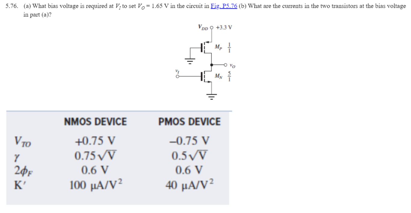
Solved 5 76 a What bias voltage is required at VI to set Chegg com

a Impact of bias voltage on measured transmission S 21 b The
Solved 76 a What bias voltage is required at VI to set Chegg com
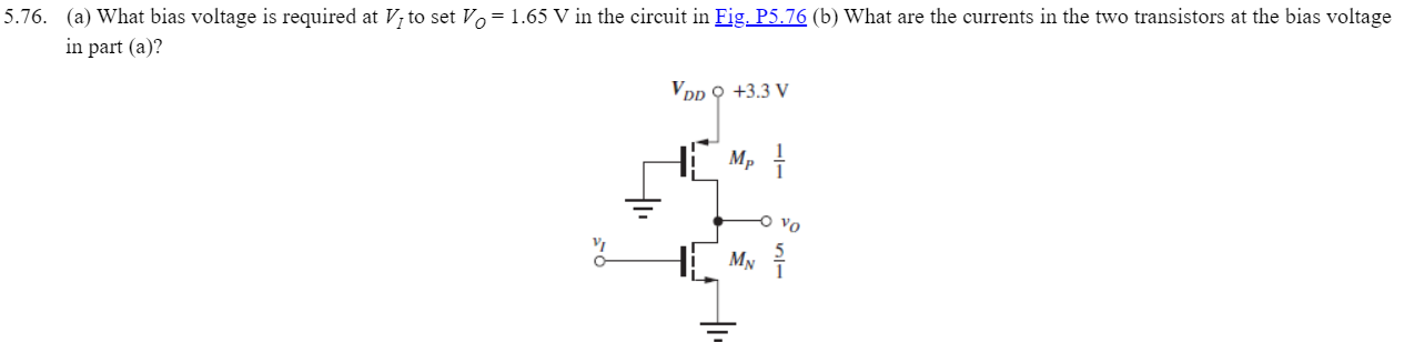
Solved 8 Let s assume that the bias voltage is set to 4 3 Chegg com
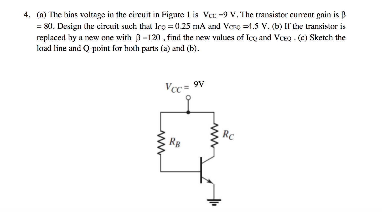
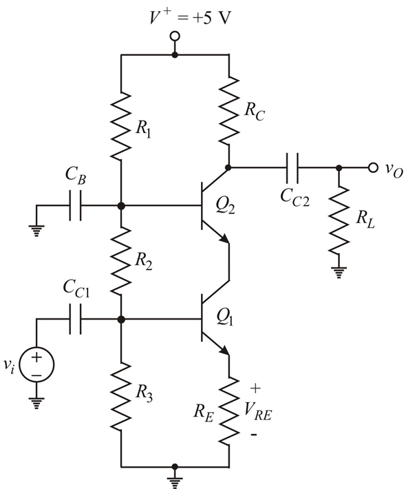
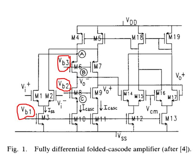
Solved 4 a The bias voltage in the circuit in Figure 1 is Chegg com
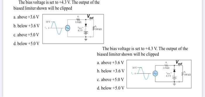
Solved The bias voltage is set to 4 3 V The output of the Chegg com

Current I as function of bias voltage V from 1 to 2 V for four
Solved 2 A bias voltage V that is within the parameters of Chegg com

Scheme illustrating the system shown in figure 1 under a voltage bias V
Solved The bias voltage in the circuit shown in Figure 5 63 is ch
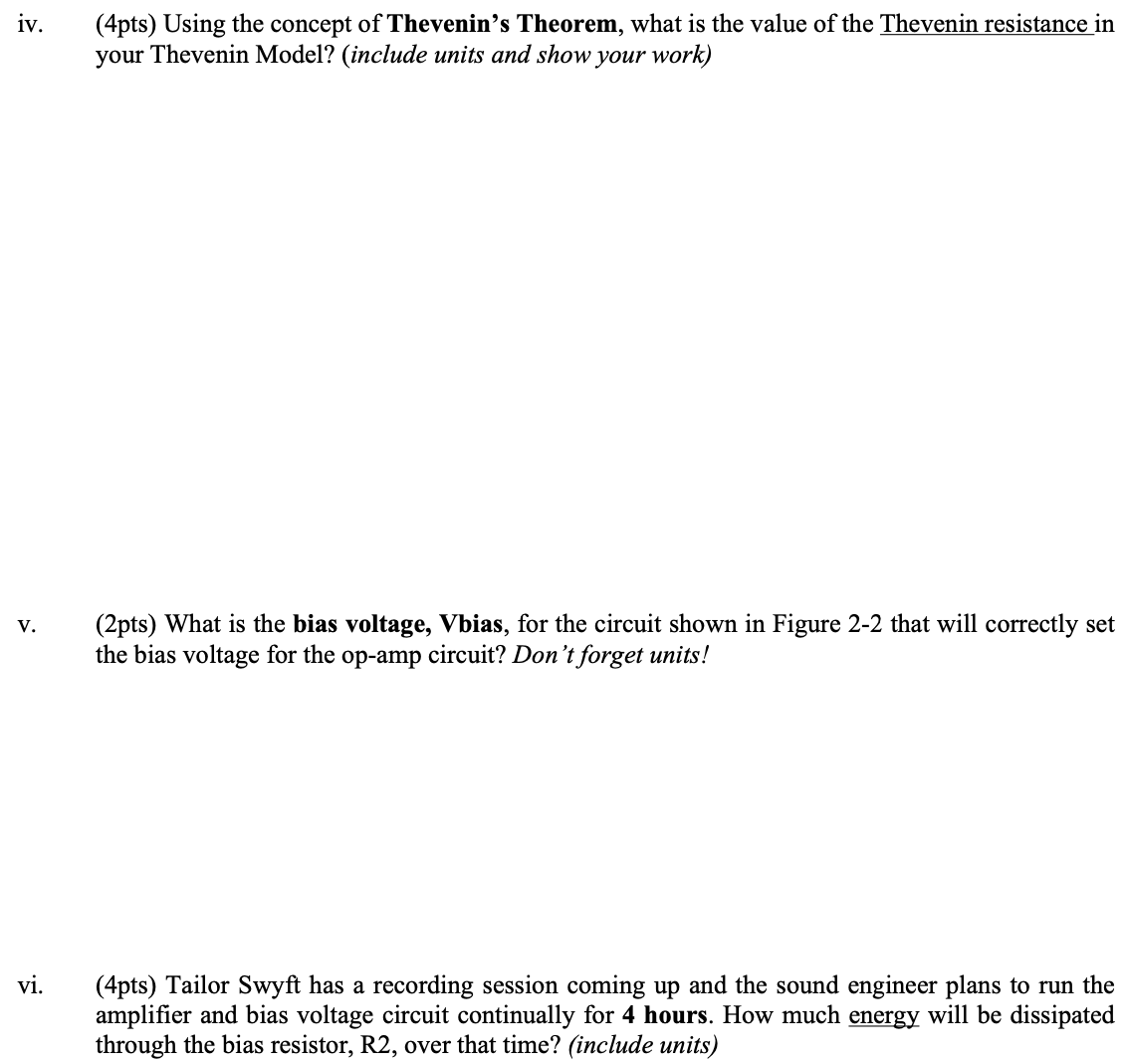
Solved 4pts For this bias voltage circuit design the team Chegg com

a Responsivity as function of bias voltage V for TM and TE

The bias voltage eV dependence of the noise response in the

Bias voltage dependent aC A V documentclass 12pt minimal

a Responsivity as function of bias voltage V for TM and TE

Same as in Fig 4 a and b but for bias voltage V CC 2 V and
Solved The bias voltage in the circuit shown in Figure 5 63 is ch
Solved 4pts For this bias voltage circuit design the team Chegg com
a Responsivity as function of bias voltage V for TM and TE
The bias voltage eV dependence of the noise response in the
Bias voltage dependent aC A V documentclass 12pt minimal
a Responsivity as function of bias voltage V for TM and TE
Same as in Fig 4 a and b but for bias voltage V CC 2 V and

a C 2 as a function of bias voltage of the devices based on 2D 3D

The current through the actuator as a function of applied bias voltage

The proposed setup An applied bias voltage V between the source S and

Current versus bias voltage calculated for three spin configurations at

I out I in as a function of the bias voltage Here I out I 1 I

a Current through the device as a function of bias voltage at

Self bias voltage as function of time for several CH4 injected amounts

a Schematic of the measurement setup A bias voltage V b is applied
Lower part variation with the bias voltage at 4 26 K of the normalized

Relationship between the bias voltage and the received signals and the

Relationship between the bias voltage and the received signals and the

a I V characteristic for bias voltage in the range of 0 3

with different bias voltages Download Scientific Diagram

a Reference measurements for different bias voltages applied to the
Solved Hello I have here 3 bias voltages how should i Chegg com

S 21 at different bias voltages Download Scientific Diagram

Bias voltages at different nodes in the circuit Download Scientific

Output tube bias current monitoring and more Page 2 diyAudio
Driving acceptance of electric vehicles BOI Board of Innovation
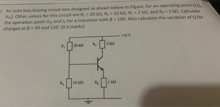
Solved An auto bias biasing circuit was designed as shown Chegg com

Variations in the bias startup output voltages V and V following a
What Is Bias Voltage Automotive - The pictures related to be able to What Is Bias Voltage Automotive in the following paragraphs, hopefully they will can be useful and will increase your knowledge. Appreciate you for making the effort to be able to visit our website and even read our articles. Cya ~.
