

Bias Voltage diyAudio
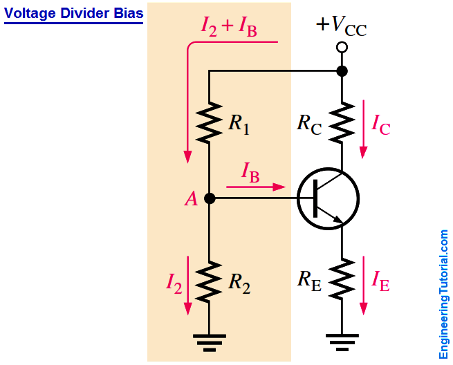
Transistor Voltage Divider Bias Engineering Tutorial

44 Bias voltage versus temperature Download Scientific Diagram
What is Bias Voltage
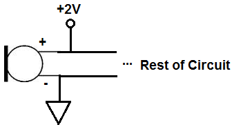
What is Bias Voltage
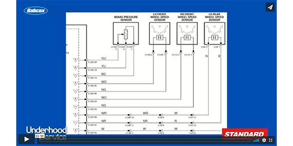
VIDEO Understanding Bias Voltage
36+ Images of What Is Bias Voltage

Gallery of What Is Bias Voltage :

5 Bias current I bias plotted versus the bias voltage V bias at a V
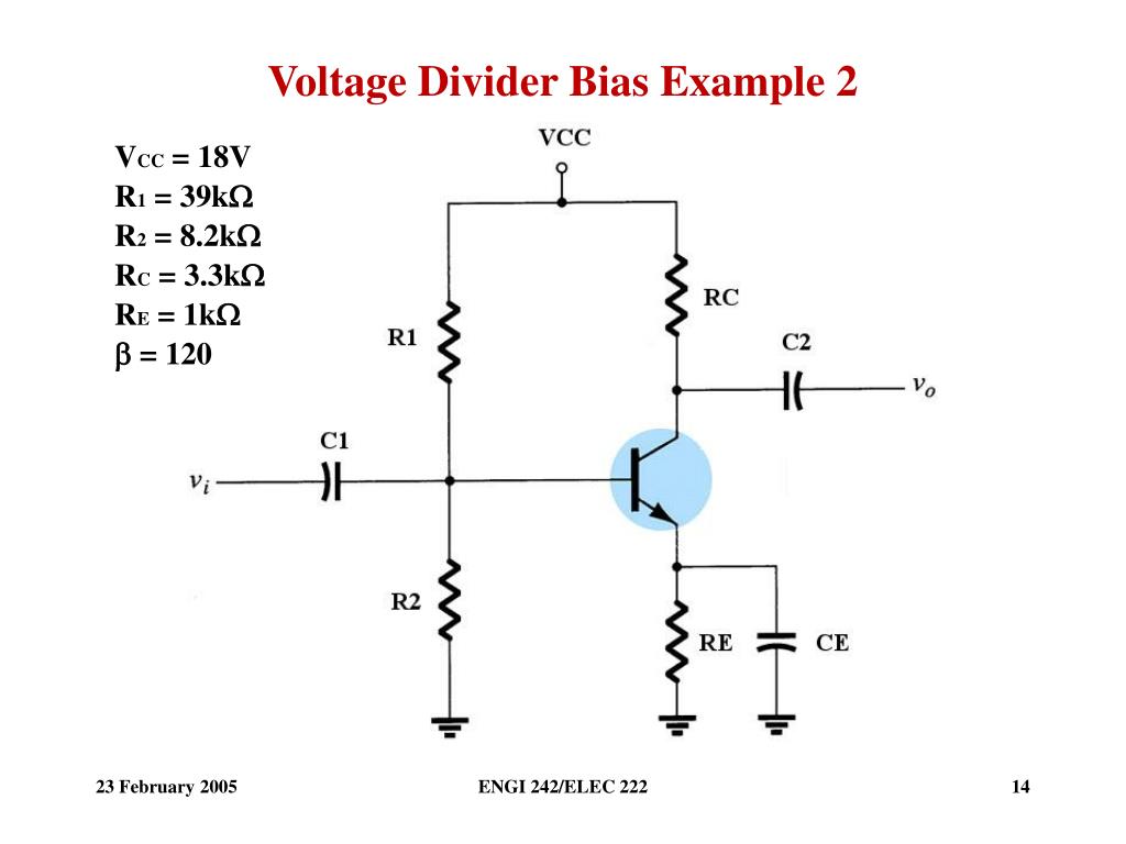
PPT Voltage Divider Bias PowerPoint Presentation free download ID

a Schematic illustration of voltage bias activation b Photograph

Current bias voltage characteristics of Device 1 a Measured

a Current across the device at bias voltage V bias 1 mV versus gate

Varying the bias voltage in constant bias experiments The pulse
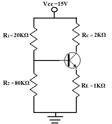
Voltage Divider Bias of a BJT Transistor
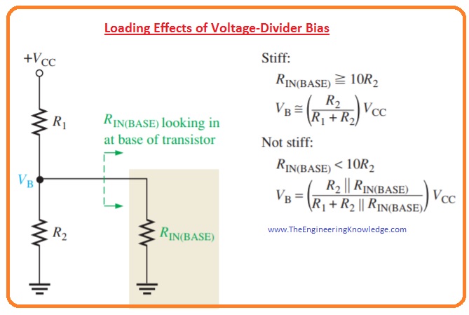
Transistor BJT Voltage Divider Bias The Engineering Knowledge

Current voltage characteristics under reverse bias Download
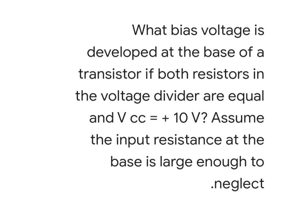
Solved What bias voltage is developed at the base of a Chegg com

The bias voltage output at v w 0 Download Scientific Diagram

The effect on the signal of the bias voltage Download Scientific Diagram

Three typical types of bias voltage V schemes a The floating bias
Current as a function of bias voltage for Download Scientific Diagram

The bias voltage that is used for the different sensors and the number

a Sample voltage V versus bias voltage Vappl at different

The electric current as a function of bias voltage at Download
Electronic schematic of the bias voltage system Download Scientific

Electronic schematic of the bias voltage system Download Scientific

FIG S2 a Voltage bias sequence applied to measure panel b First
Three typical types of bias voltage V schemes a The floating bias
Current as a function of bias voltage for Download Scientific Diagram
The bias voltage that is used for the different sensors and the number
a Sample voltage V versus bias voltage Vappl at different
The electric current as a function of bias voltage at Download
Electronic schematic of the bias voltage system Download Scientific
Electronic schematic of the bias voltage system Download Scientific
FIG S2 a Voltage bias sequence applied to measure panel b First

2 The Position of 216 m at different bias voltage V 1

Same as Fig 4 only for bias voltage V CC 2 V and excitation level

a Schematic measurement setup A bias voltage V b is applied across
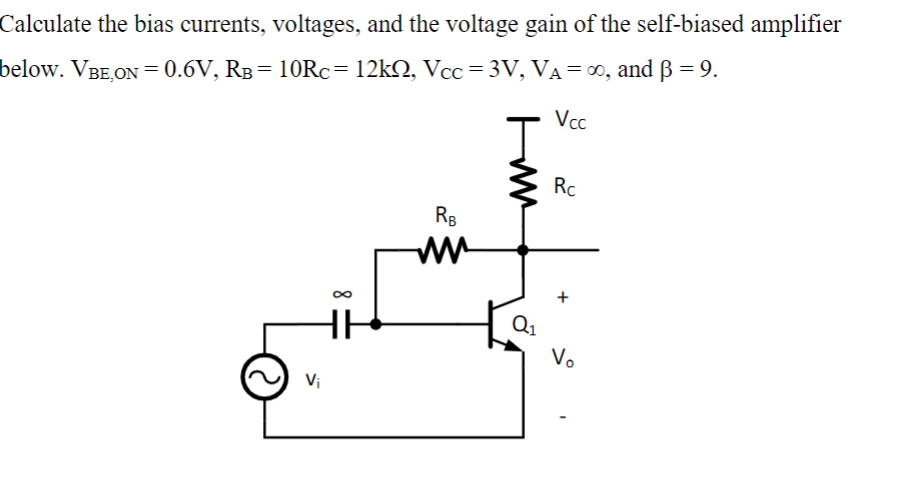
Solved Calculate the bias currents voltages and the Chegg com

Measurement of the bias voltage V B top and bias current I B bottom
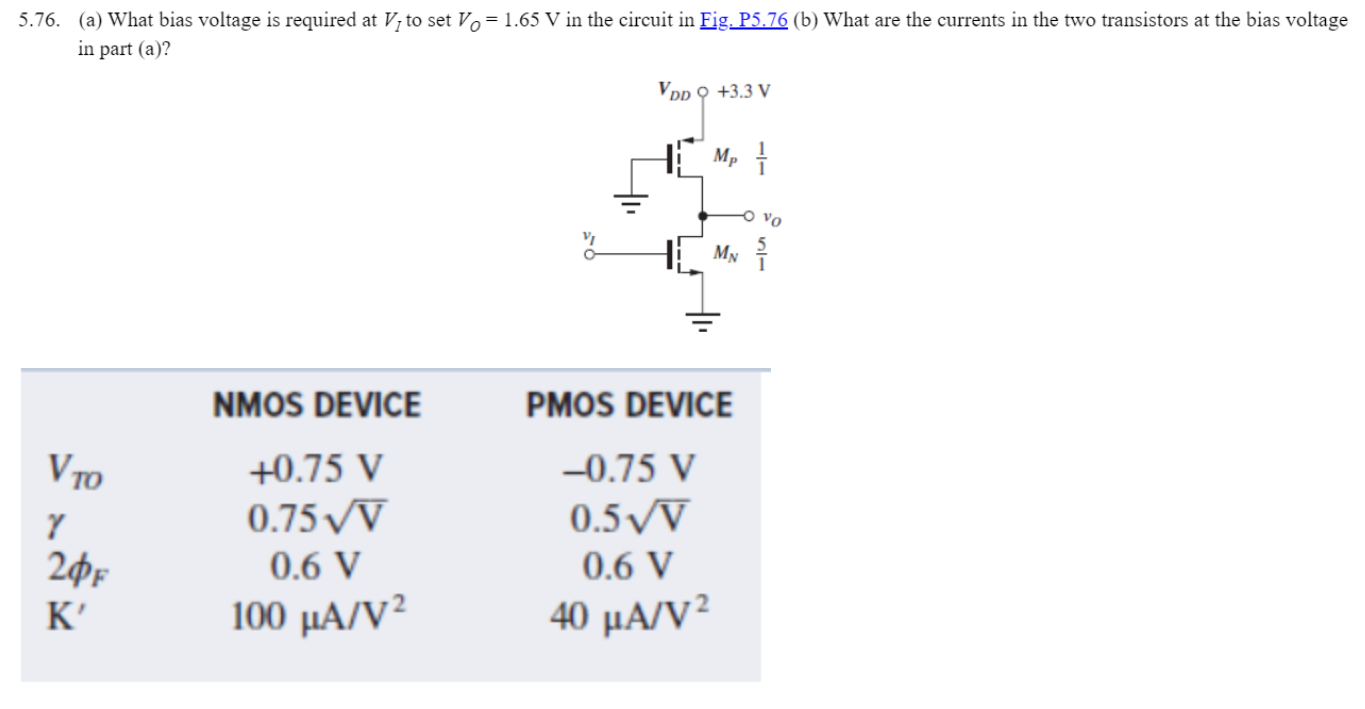
Solved 5 76 a What bias voltage is required at VI to set Chegg com
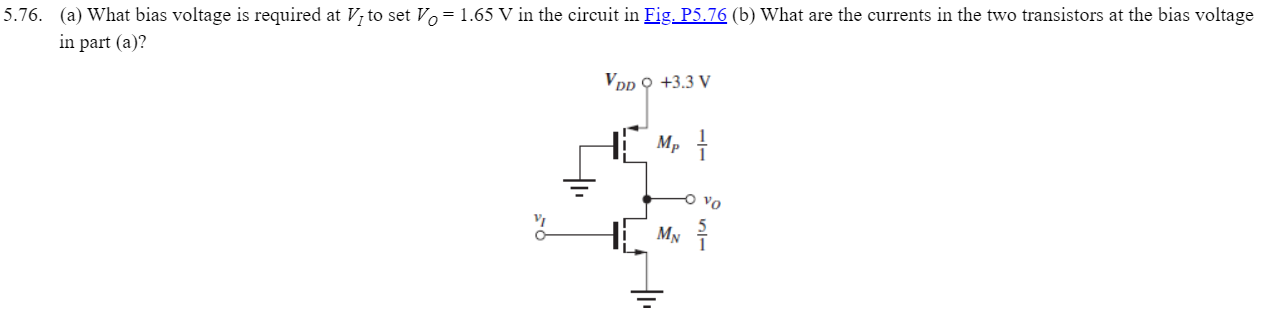
Solved 76 a What bias voltage is required at VI to set Chegg com
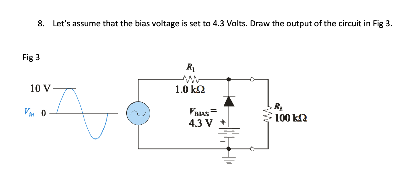
Solved 8 Let s assume that the bias voltage is set to 4 3 Chegg com

a The current voltage characteristics and b the zero bias
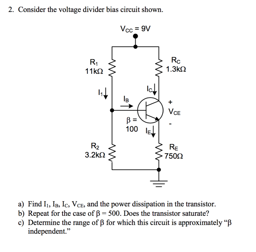
Solved Consider the voltage divider bias circuit shown Chegg com
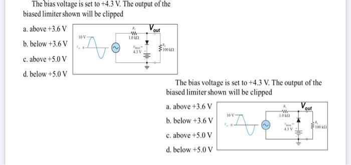
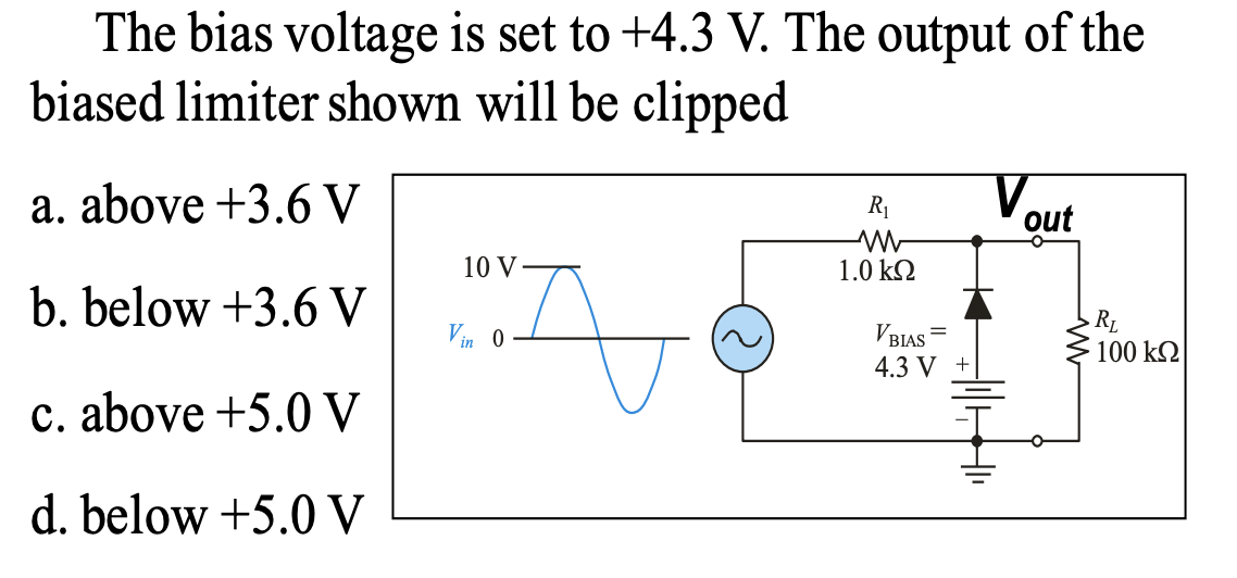
Solved The bias voltage is set to 4 3 V The output of the Chegg com

Current I as function of bias voltage V from 1 to 2 V for four
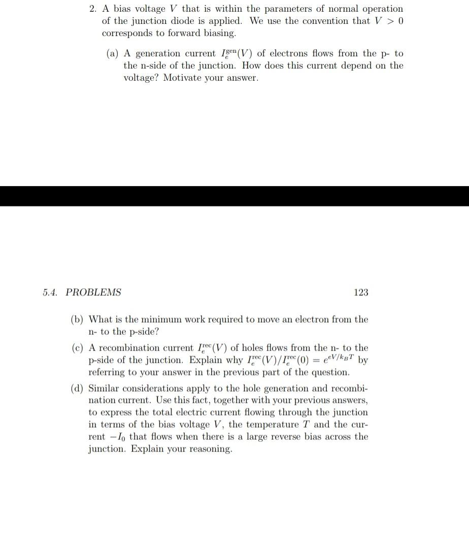
Solved 2 A bias voltage V that is within the parameters of Chegg com

Scheme illustrating the system shown in figure 1 under a voltage bias V

Diagram of the circuitry involved in measuring the bias voltage and the
Solved The bias voltage in the circuit shown in Figure 5 63 is ch

color online a SET biased by a voltage V bias The charge in the

Same as in Fig 4 a and b but for bias voltage V CC 2 V and

a C 2 as a function of bias voltage of the devices based on 2D 3D

Current versus bias voltage calculated for three spin configurations at
Scheme illustrating the system shown in figure 1 under a voltage bias V
Diagram of the circuitry involved in measuring the bias voltage and the
Solved The bias voltage in the circuit shown in Figure 5 63 is ch
color online a SET biased by a voltage V bias The charge in the
a C 2 as a function of bias voltage of the devices based on 2D 3D
Same as in Fig 4 a and b but for bias voltage V CC 2 V and
Current versus bias voltage calculated for three spin configurations at

I out I in as a function of the bias voltage Here I out I 1 I

Bias voltage modified I V characteristics of a varistor with I d
Answered The bias voltage is set to 4 3 V The bartleby

a Current through the device as a function of bias voltage at

a Schematic of the measurement setup A bias voltage V b is applied
Lower part variation with the bias voltage at 4 26 K of the normalized

Relationship between the bias voltage and the received signals and the

Relationship between the bias voltage and the received signals and the

a I V characteristic for bias voltage in the range of 0 3

with different bias voltages Download Scientific Diagram

with different bias voltages Download Scientific Diagram

a Reference measurements for different bias voltages applied to the
Solved The bias voltages in the circuit shown in Figure 5 34 Chegg com
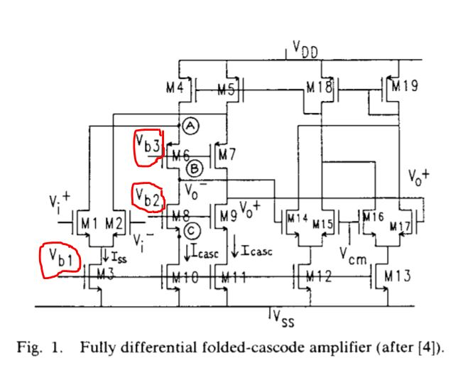
Solved Hello I have here 3 bias voltages how should i Chegg com
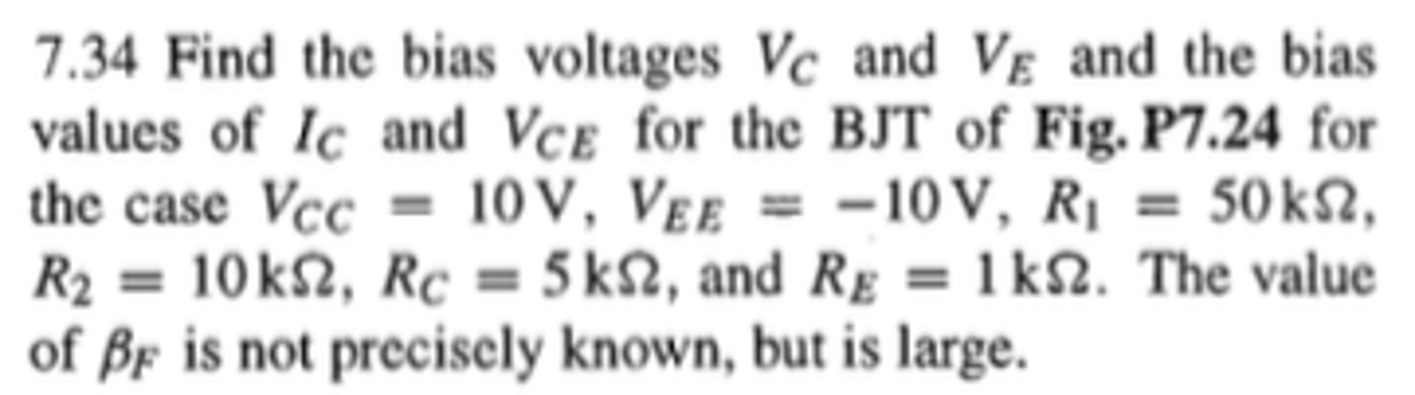
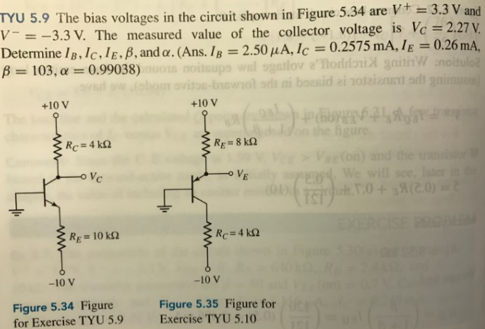
Solved Find the bias voltages V c and V E and the bias Chegg com

Voltage Divider

S 21 at different bias voltages Download Scientific Diagram

Bias voltages at different nodes in the circuit Download Scientific
Solved Obtain the bias voltages and currents of the circuit Chegg com
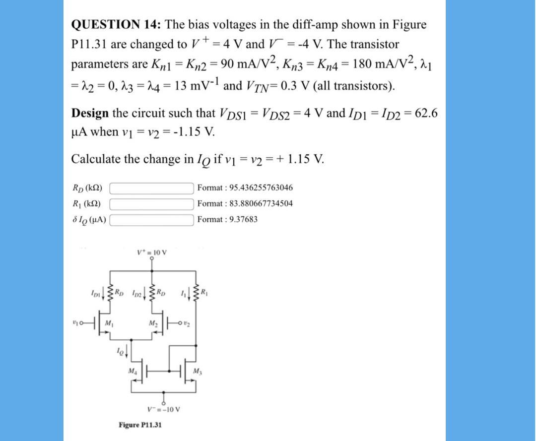
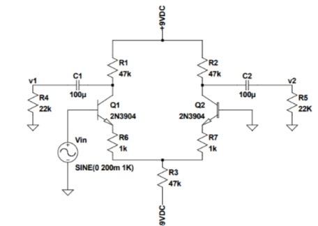
Solved QUESTION 14 The bias voltages in the Chegg com

For a circuit the bias voltages are changed to V 3 ma Quizlet
What Is Bias Voltage - The pictures related to be able to What Is Bias Voltage in the following paragraphs, hopefully they will can be useful and will increase your knowledge. Appreciate you for making the effort to be able to visit our website and even read our articles. Cya ~.
